Generator Exhaust - Large Diameter Pipes for Industrial Generators
Introduction A system designer must consider environmental and performance criteria when sizing and positioning the exhaust system of a generator set. Correct installation of the exhaust is also crucial to ensuring full performance of the engine. This info sheet is a guide and discusses the issues to be addressed when installing a generator set’s exhaust system.

Key purpose of the exhaust system: All engine systems have exhaust systems to facilitate: Safe evacuations of gases - Exhaust gases for safety and environmental concerns should be safely vented to atmosphere for both inside and external locations. Sound attenuation - Various muffler grades are available to meet different acoustic requirements. Engine performance - Incorrect exhaust sizing can result in degraded engine performance.
Safe evacuation of exhaust gases: When designing a system the following should be noted:
• To prevent re-circulation of gases into other areas outlets should be located upwind and away from any building and equipment air intakes. Engine exhaust can also be a fire hazard and must never be exhausted adjacent to any combustible material.
• Pipe sleeve or fire proof materials are used when exhaust pipes pass through building material.
• Local codes should be consulted by the designer.
Sound attenuation: When designing a system the following should be noted:
• Consult local codes for sound level limitations. Generator set manufacturers offer four types of silencers, industrial, residential, critical and hospital for very noise sensitive locations.
• Consult the attenuation curves given for a silencer to ensure it is within code
Engine performance: The manufacturer can detail the maximum allowable back pressure or restriction with the system. It is specified as “inches hg”. When the back pressure is exceeded, the air-fuel ratio is reduced which results in a drop in fuel economy and power output. The following should be undertaken:
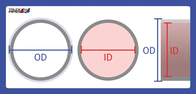
• The designer, having the manufacture’s data for gas flow (ft³/min) and maximum back pressure, uses a chart to determine the inside diameter of the pipe.
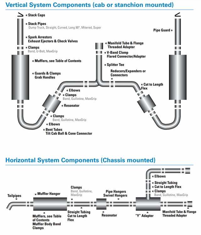
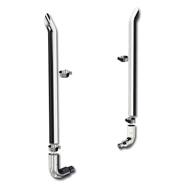
• The exhaust system should be designed as short as possible with a minimum of bends. A 90° pipe bend increases the length of the system and back pressure.
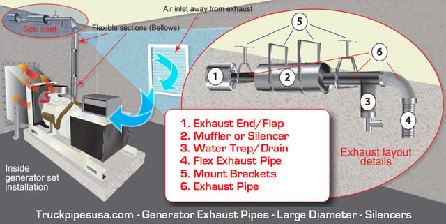
Exhaust system criteria: The designer of the system should also consider the exhaust factors in the design: Water in the system - Water can be a by-product of exhaust and enter the system as rain. To prevent water from draining back into the system, slant the horizontal pipe away from the engine and install a water trap at the lowest point.
A rain cap should be fitted on exhaust pipes ending in the vertical position.
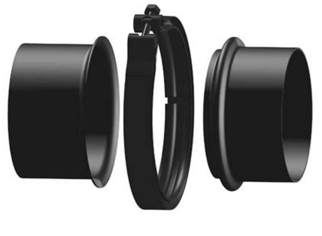
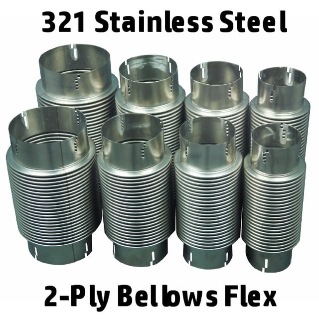
Flexible exhaust sections - To prevent damage due to vibration and thermal expansion, flexible bellow type sections should be installed. Do not use bellows for required bends and alignment adjustment.
Soot deposits - For environmental and aesthetic reasons consider placement of the exhaust outlet to avoid exhaust gas deposits accumulating on adjacent structures/buildings. Exhaust structure - The exhaust system weight should be adequately supported and utilize robust material such as 304 Stainless Steel or Cold Rolled Steel Heavy Gauge.
The systems can be supported by various means but must remain flexible and the weight should never be carried by the engine manifold and/or turbo-charger.
Galvanized piping should never be used in an exhaust system.
Wind effect - Consider the prevailing wind at the required locations and position the exhaust outlet to avoid exhaust gases being returned into the generator set installation or entering other structures.